3 Circuit Assembly System
To automatically assemble these geometries, a motion system and end effector suitable for reliably manipulating these geometries is necessary. The two most viable approaches are mechanically gripping and retaining by friction, and pneumatic pick up.
In this chapter, the assembly system will be described and specific modifications for each geometry detailed. Geometries will then be compared and contrasted on their ease of scalability.
Scalability refers to ease of automated assembly, including fabrication and assembly of the elements (tiles and connectors) themselves, and assembly of circuits using the elements as feedstock. Yield at each stage is important, as well as cycle times.
To implement applications of sufficient complexity, circuits on the order of at least 100s of elements need to be assembled, as partially demonstrated from the related work described in Chapter 1. In our context, 10s of tiles are enough to demonstrate basic functional circuits, such as a NAND gate or ring oscillator, 100s of tiles are enough to demonstrate a full-adder, an important functional block towards a computer.
3.1 Assembly
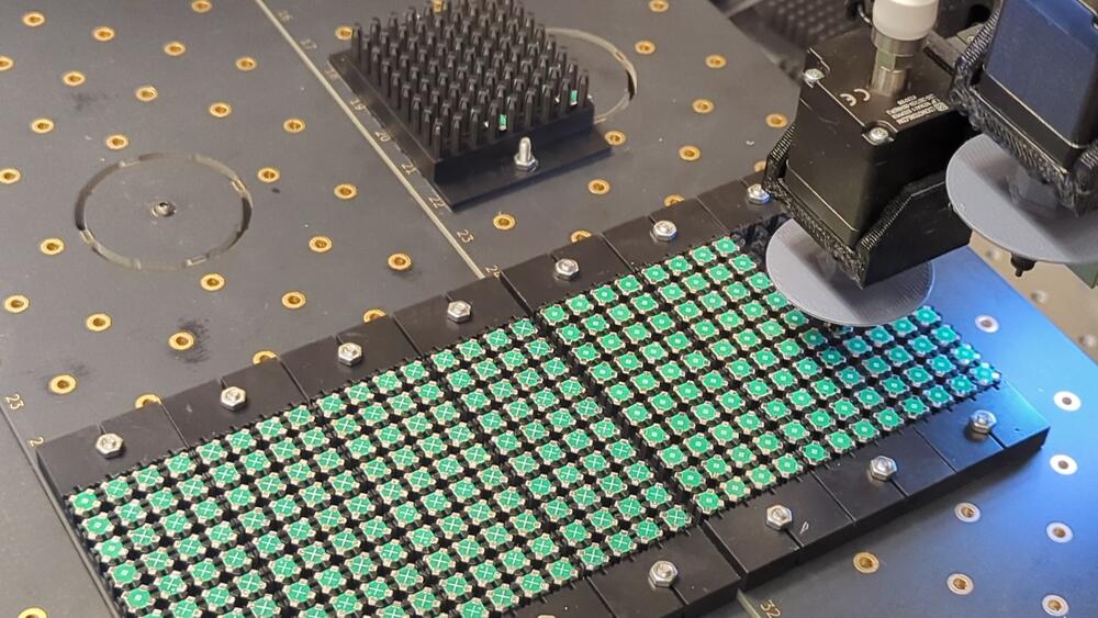
Over the course of assembly testing, multiple placement benchmarks were achieved, starting from 4Hp. The majority of the benchmarks were conducted using the 4BI geometry, since it is designed to scale better. These benchmarks are shown in Figure 3.8.
The flow of operations for assembly of VMD circuits is essentially the same as using a traditional pick-and-place, but adjusting the z of successive components for each additional layer (Figure 3.2).
3.1.1 Setup
First, the feeders and substrate are installed into the machine. These are currently Form 4 Black V5 resin prints that have been printed flat on the bed; this makes sure that surfaces are as flat as possible from the printer and precludes need for support. They are installed using M3 screws and nuts.
Then, tiles are loaded into feeders, organized by type, with consistent orientation.
Next, the substrate (build platform) is installed. I try to keep the feeders and substrate relatively close to reduce travel time. If the cameras are being used, that’s a good place to locate them near, but the stock configuration seems to put more tension on the camera/main platform for the LumenPnP so I prefer to use the auxiliary platforms for my substrate and feeders.
With everything installed, I pass a pnp job (.pos, or .board.xml, the native OpenPnP format for jobs) into OpenPnP, run calibration on the feeders and substrate, and press go.
3.1.2 Operation
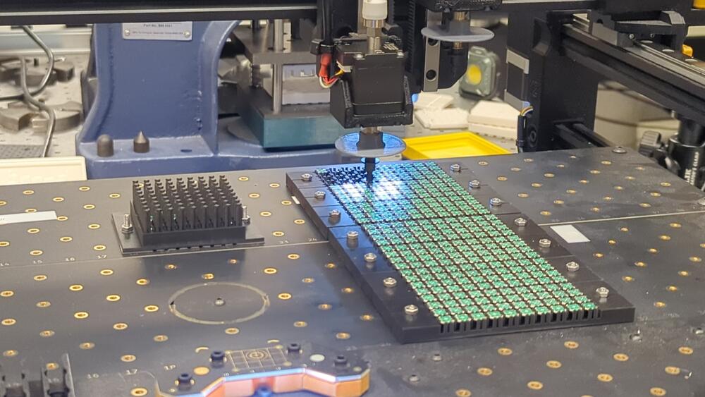
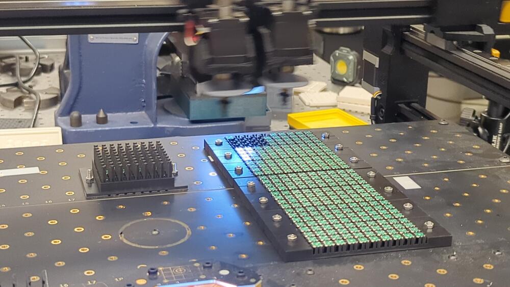
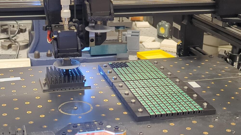
The head moves to the feeders, picks up a part, goes to computer vision, checks part orientation, goes to substrate, places part, and repeats this process until job finish, or as a fault occurs. The basic steps are shown in Figure 3.3.
3.2 Motion System
Off-the-shelf open source desktop pick and place machines have matured to the point that it makes sense to use that as a starting point and see how far assembly can be scaled using this motion system. Designing around an existing system allows us to allocate more resources towards geometry development relative to the assembly system.
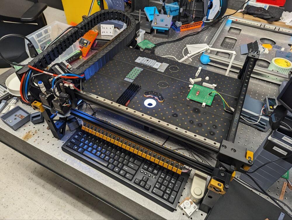
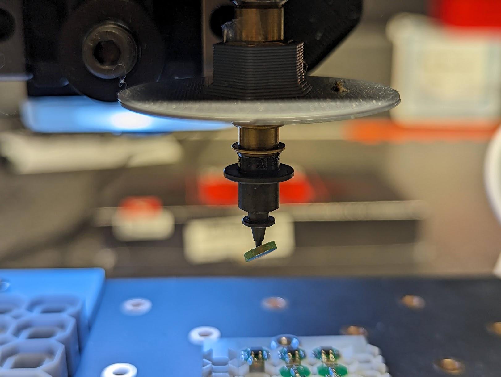
The LumenPnP (Figure 3.4) is a CoreXY motion system with a relatively low z travel, optimized for 2D pick and place operations. In our packaging system, the LumenPnP is used for 2.5D assembly.
3.3 Feeders
Feeding is an integral part of the assembly process; as assembly complexity increases, the need to feed higher volumes of primitives increases as well. Resetting jobs manually with tweezers becomes increasingly limiting without automation in the loop.
3.3.1 Passive Tray Feeders
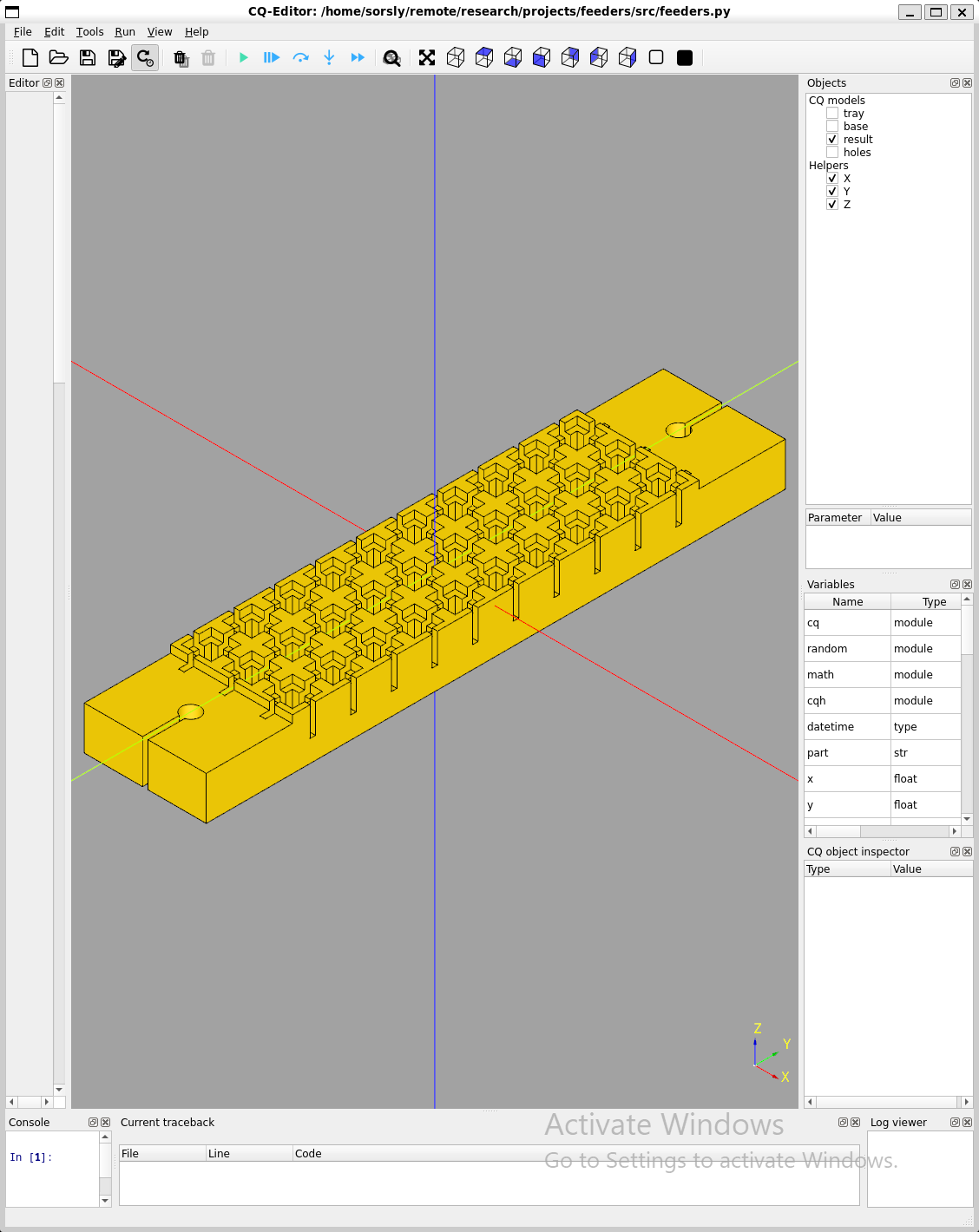
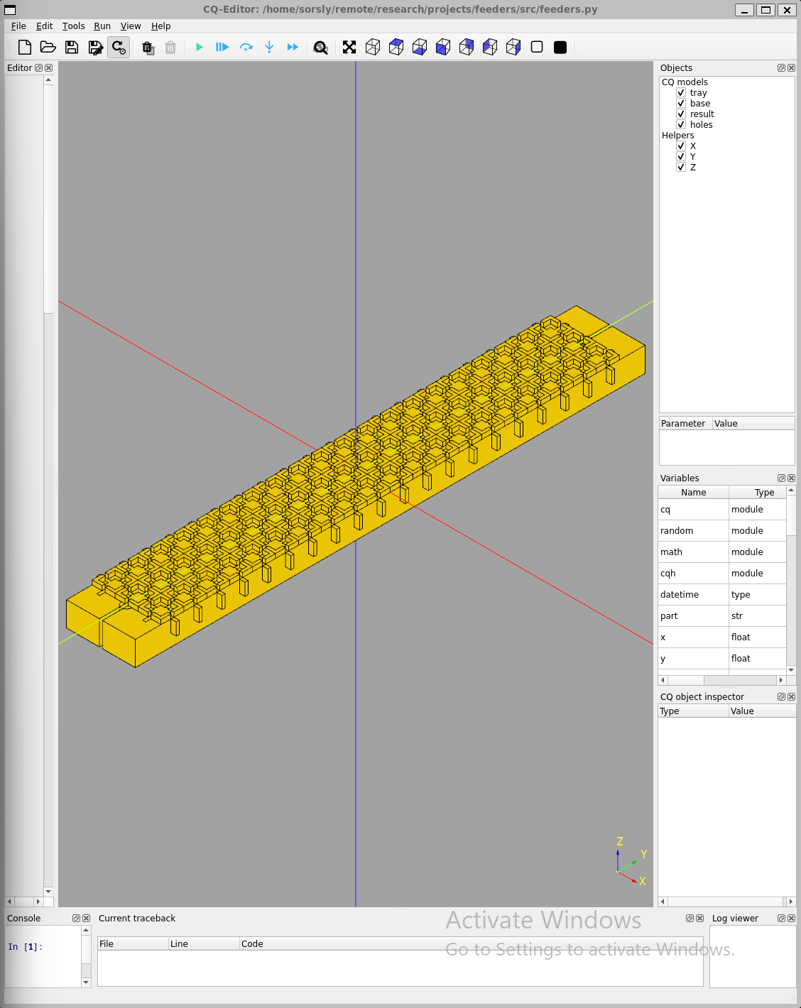
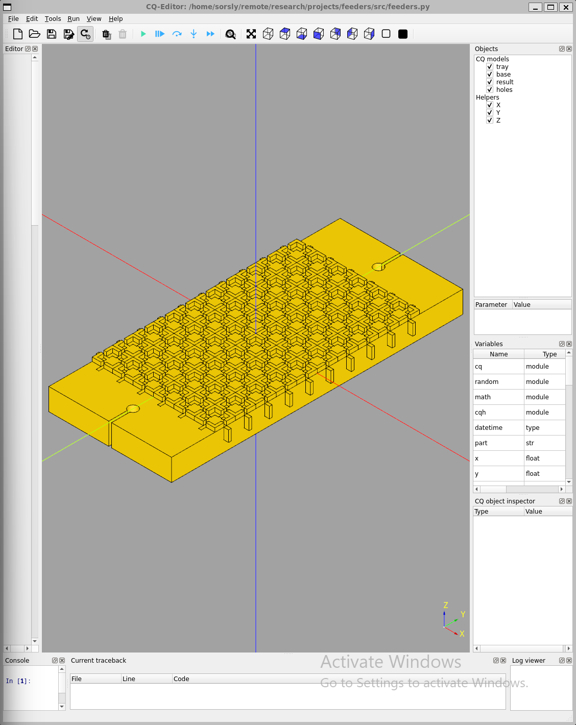
Passive tray feeders were found to be the best fit for initial pick and place operations, initially designed using solidworks, then formalized with feeders.py (cadquery), a parametric script subsequently used to generate arbitrary feeders for both the pnp process and other fab work holding and feeding.
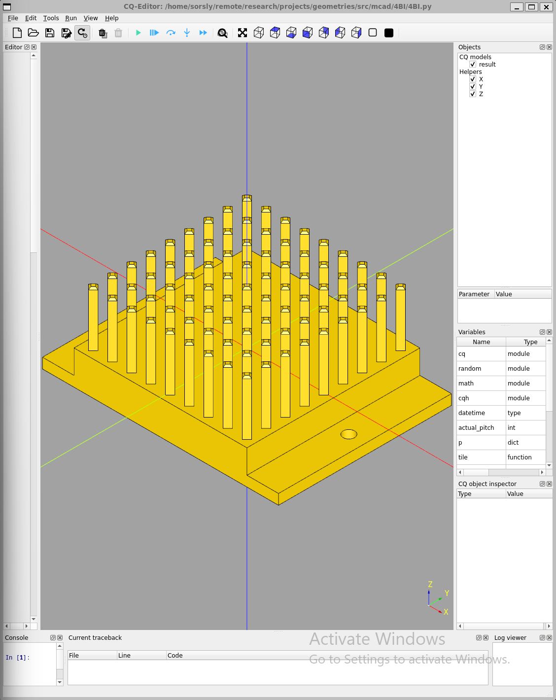
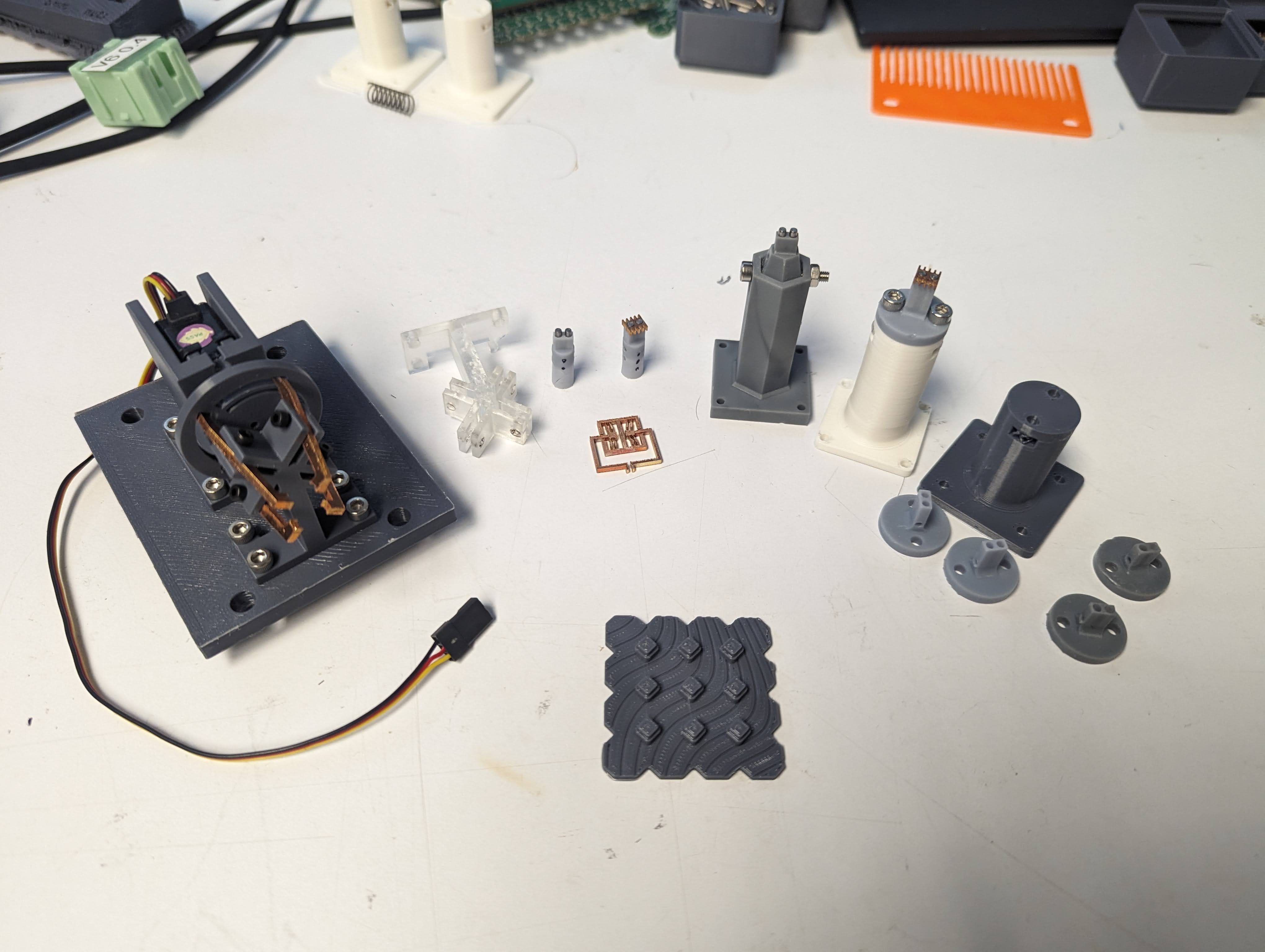
The geometry and its associated infrastructure (feeders for holding the parts, end effector to pick and place the parts, template to receive the parts), were initially designed in SolidWorks, a parametric point-and-click MCAD tool. In some cases, such as the 4Bx family templates and feeders, designs were then migrated to CadQuery 2, a parametric scripted MCAD tool. CadQuery 2 offers performance and organizational advantages, namely the python support which makes headless automation and scripting with external libraries easy (versus something like the SolidWorks or Fusion360 API). This supports our bottom-up (dice_cad) and top-down design tools designed by my colleague Erik Strand. Feeders are shown in Figure 3.5.
3.3.2 Adding Depth
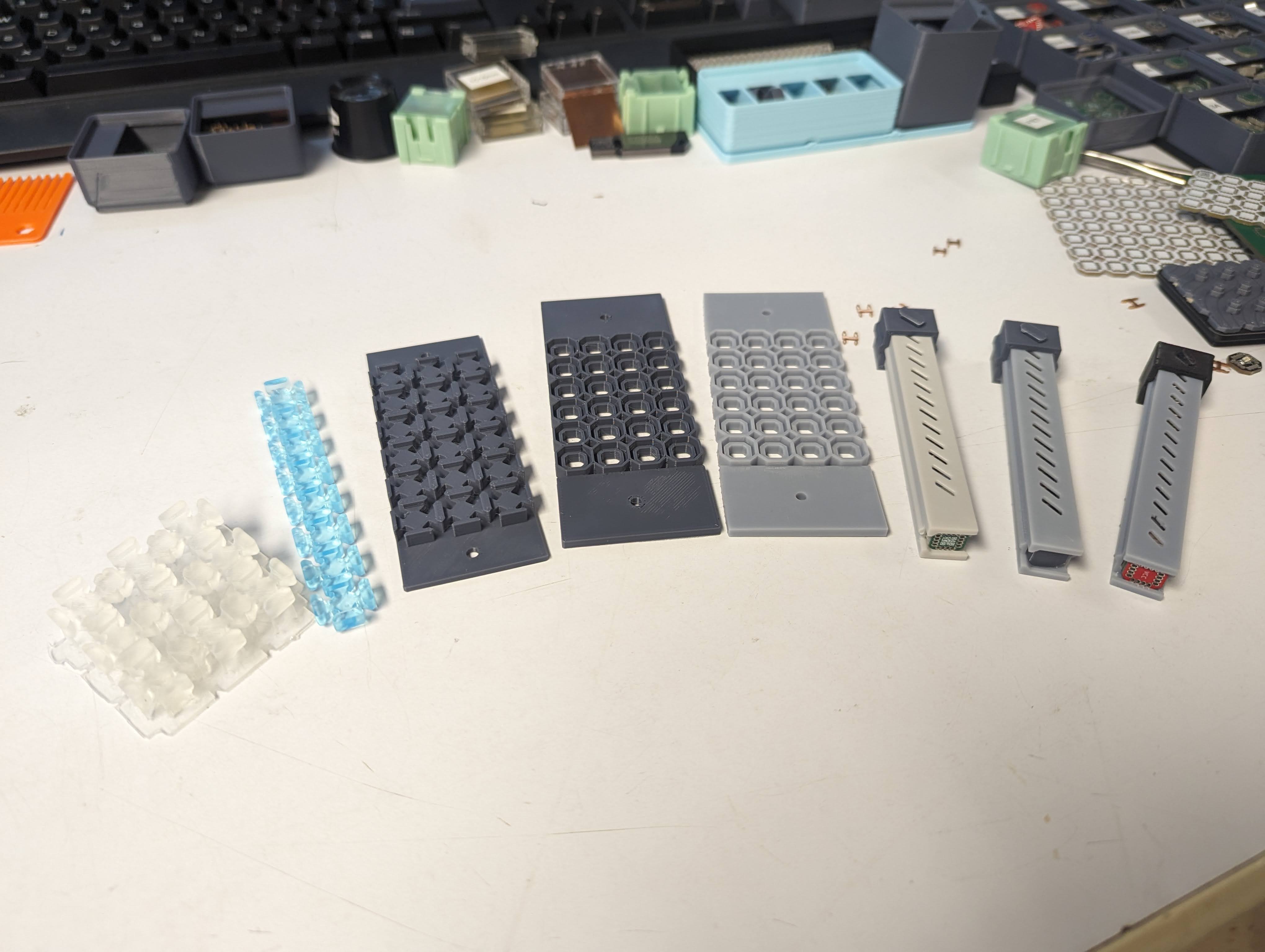
As assembly transitioned from 10s to 100s, depth was added to feeders to save on xy travel as well as pnp work area. For 4BI, a depth of 3 tiles (of 1.6mm each) was found to be a reasonable capacity; larger than 3x became difficult to load tiles in the correct orientation.
Packaging changes introduce additional challenges for feeding; simple 2d tiles (such as PCBs) have a predictable z-thickness, but packages with compliant flexures have variable z-thickness under load (4BIk) (such as during pick and place) and packages that have been balled (4BIb) (BGA) are subject to additional tolerance stackup based on control of solder sphere tolerances. For exceptionally varied packages, tile planarity also becomes an issue (4BIb?), which needs to be controlled by the feeder geometry itself.
3.3.3 Alternative Feeders
There are many other types of feeders beyond passive tray feeders, such as tape feeders, or vibratory bowl feeders. [1] Traditionally, 1000s of components are likely to be packaged in tape-and-reel. To maintain compatibility between our tiles and industry standard tape-and-reel for feeding, 8mm and 12mm wide tapes would be ideal. Tape and reel introduces additional packaging challenges and tolerance stackup. An alternative approach to active feeding of arbitrary geometries is vibratory feeders. Vibratory feeders come in a couple of flavors, including dish and linear. The main advantage of a vibratory feeder setup is being able to sort loose parts for predictable pick and place. These systems can be combined with computer vision for additional or complementary error correction of part orientation.
3.3.4 Resetting Jobs
The current tray feeders work reliably and have room for increased density. However, while they are easy to populate for jobs of 10-100 elements, they quickly become tedious to populate with tweezers, both the conventional and vaccuum types. This is especially true when considering orientation (rotationally and flipped) matters. Populating 280 tiles into 7 feeders (4x10) took ~40min by hand, and it happened that this job was purely a mechanical benchmark with dummy tiles that didn’t care about orientation; properly orienting tiles would add additional time.
One possible way to tackle this problem is to observe that feeders and templates are both forms of tile storage. Since a feeder can be used to feed tiles for a template, why can’t a template be used to feed a feeder? Feeders are optimized for packing tiles in a non-functional state for the purpose of having tiles removed, while templates are optimized for constrained structural lattices in a functional state for retaining tiles.
Storage solutions for these opposite states are easy to design for separately, but difficult to bring together; while removing tiles from a feeder should be low-force, removing tiles from a template should be difficult.
3.4 Substrates
Substrates are large feedstock used as a platform for mechanically constraining and sometimes electrically routing elements assembled into circuits. Related work from Langford [2] and [3] demonstrate uses of substrates for preloading and alignment of elements as well. Two major types of substrates were explored over the course of the geometry design study, the macro-tile from 4Hp, and the template from 4BI.
3.4.1 4Hp Macro-tile
The 4Hp macro-tile (Figure 3.6) both provided mechanical support and enabled electrical routing and made breaking out signals easy. Additionally, it was designed with edge tolerances in mind such that tesselating macro-tiles was possible, enabling larger circuits beyond a single macro-tile. However, it made automation difficult; the through-hole connections used to interface with H-eon connectors required higher tolerances, which weren’t possible to achieve at scale through the fabrication of H-eon connectors. In addition, 4Hp relied on high insertion forces; this caused the assembler to skip steps during insert, which meant rehoming between each place. In cases of misalignment, this also caused the macro-tile to kinetically discharge chunks of FR4.
Because the macro-tile was a PCB following standard PCB design rules, it wasn’t possible to improve lead-in by chamfering the through holes.
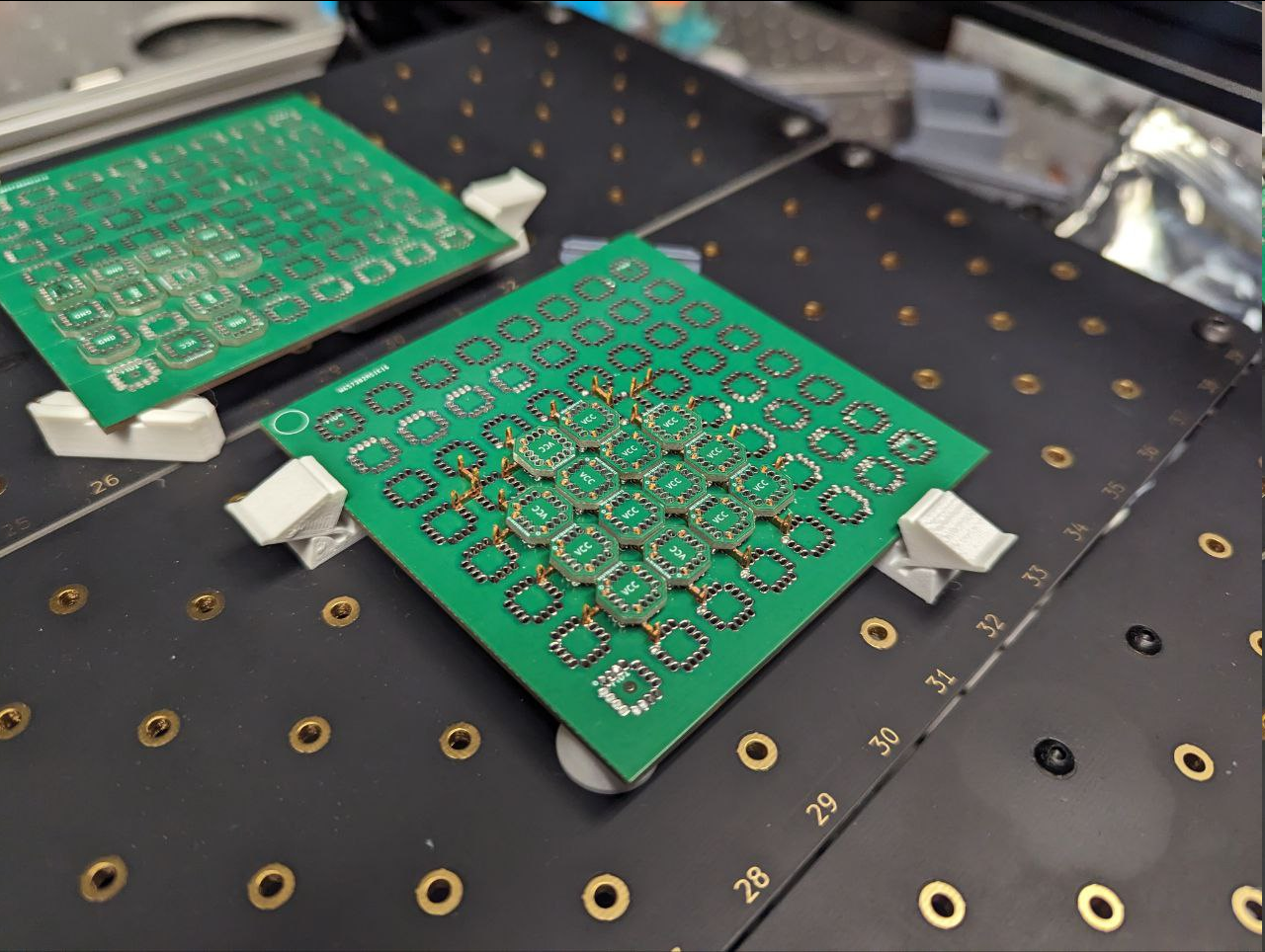
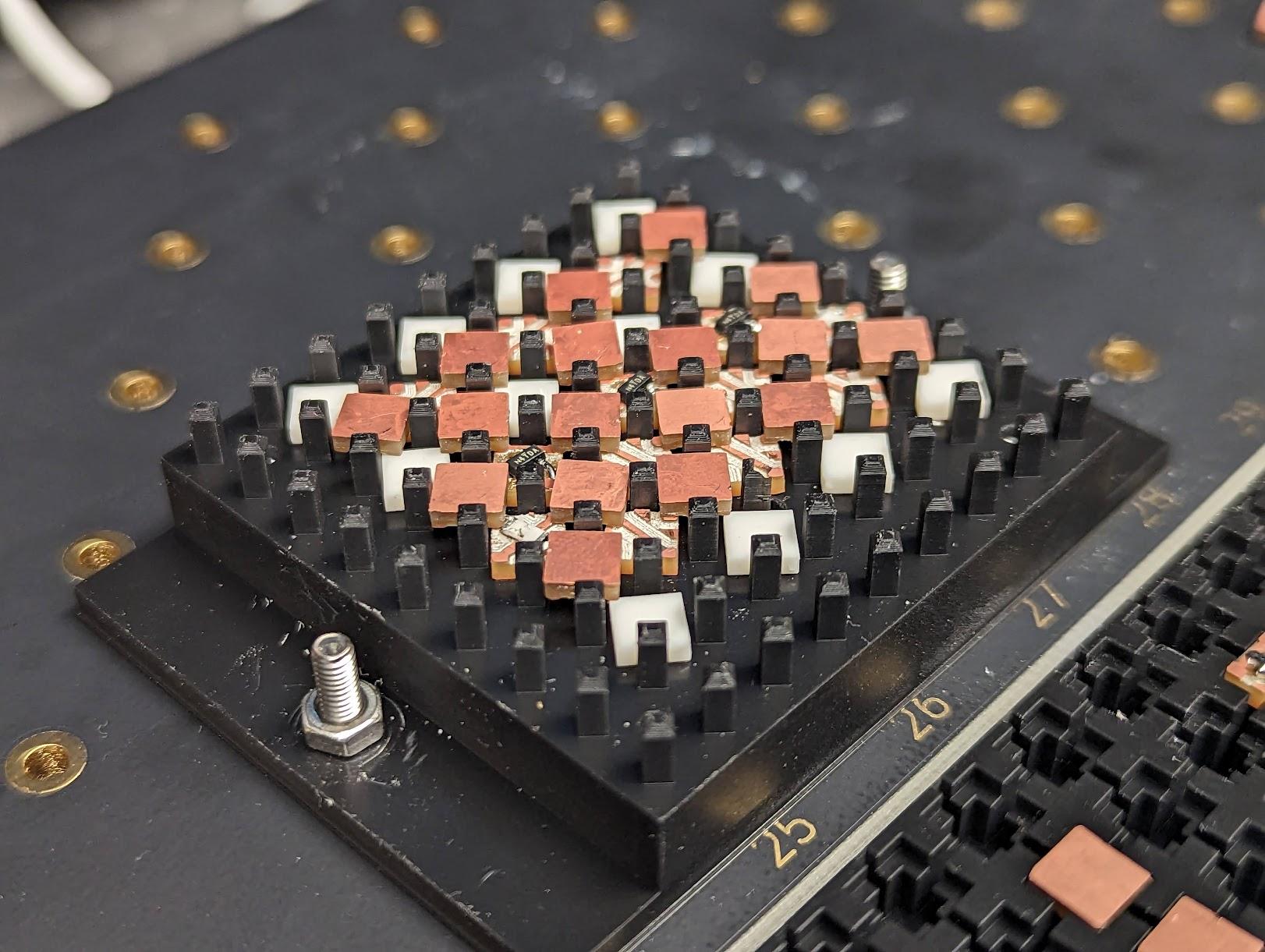
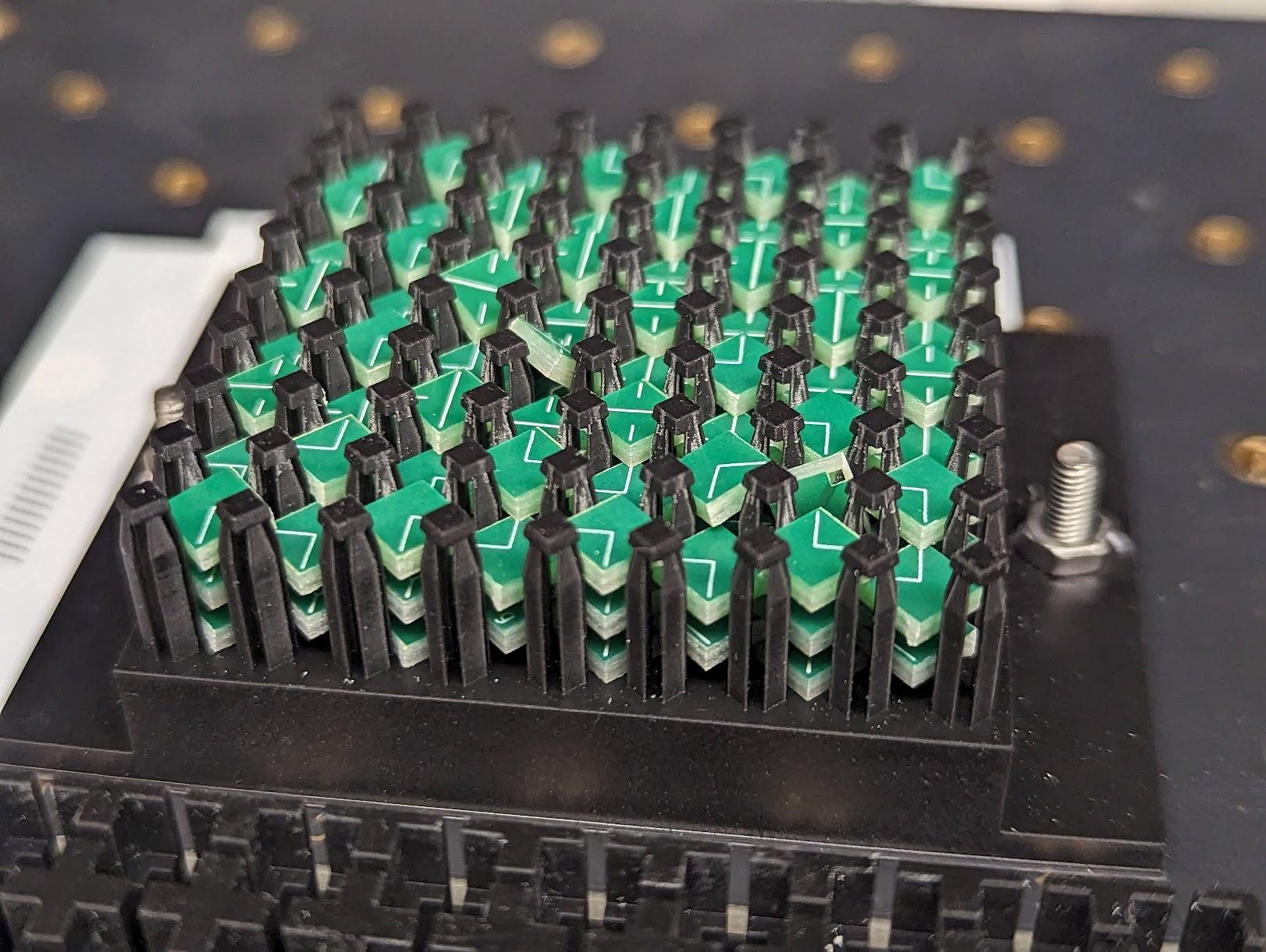
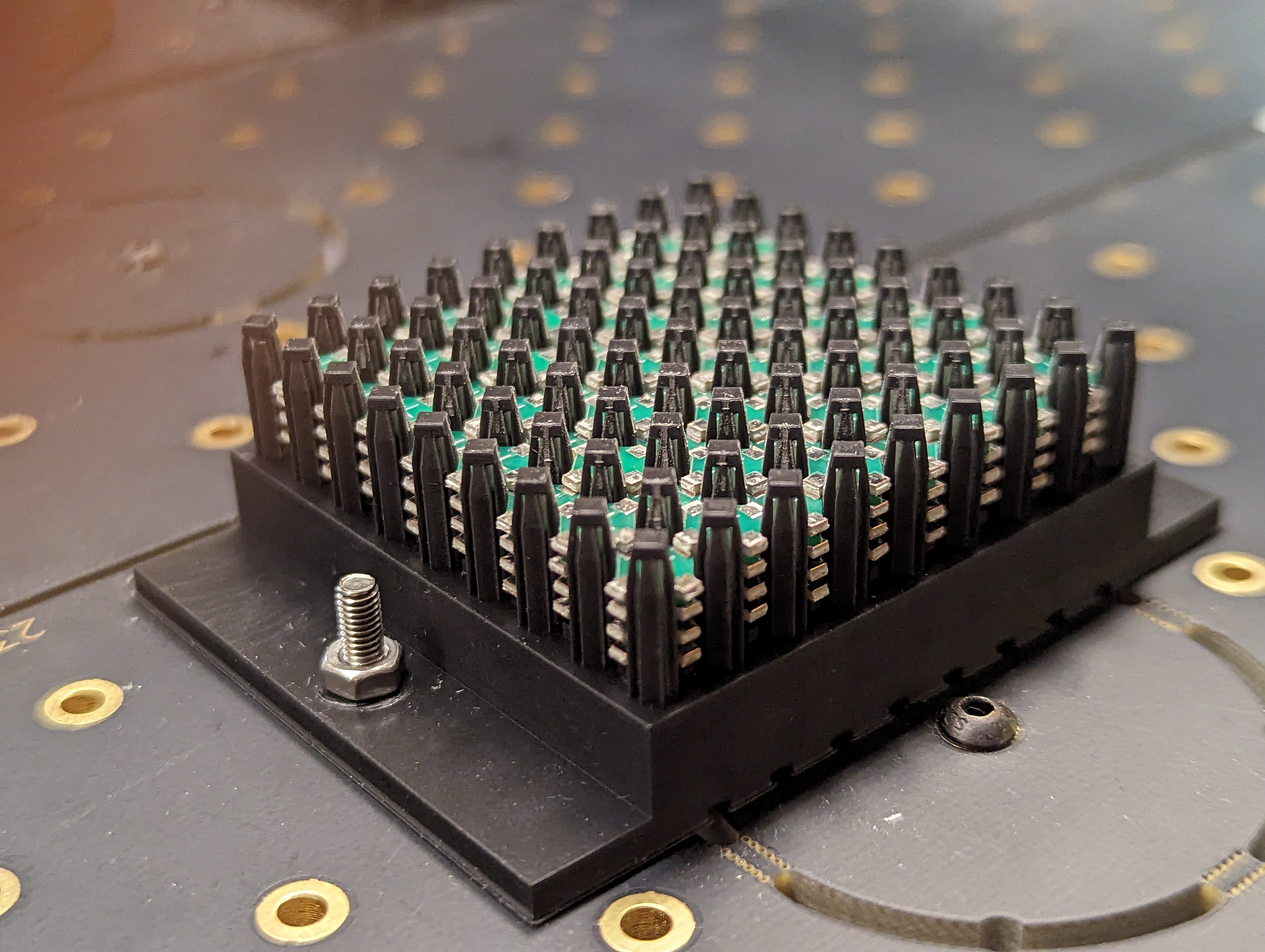
3.4.2 4BI Template
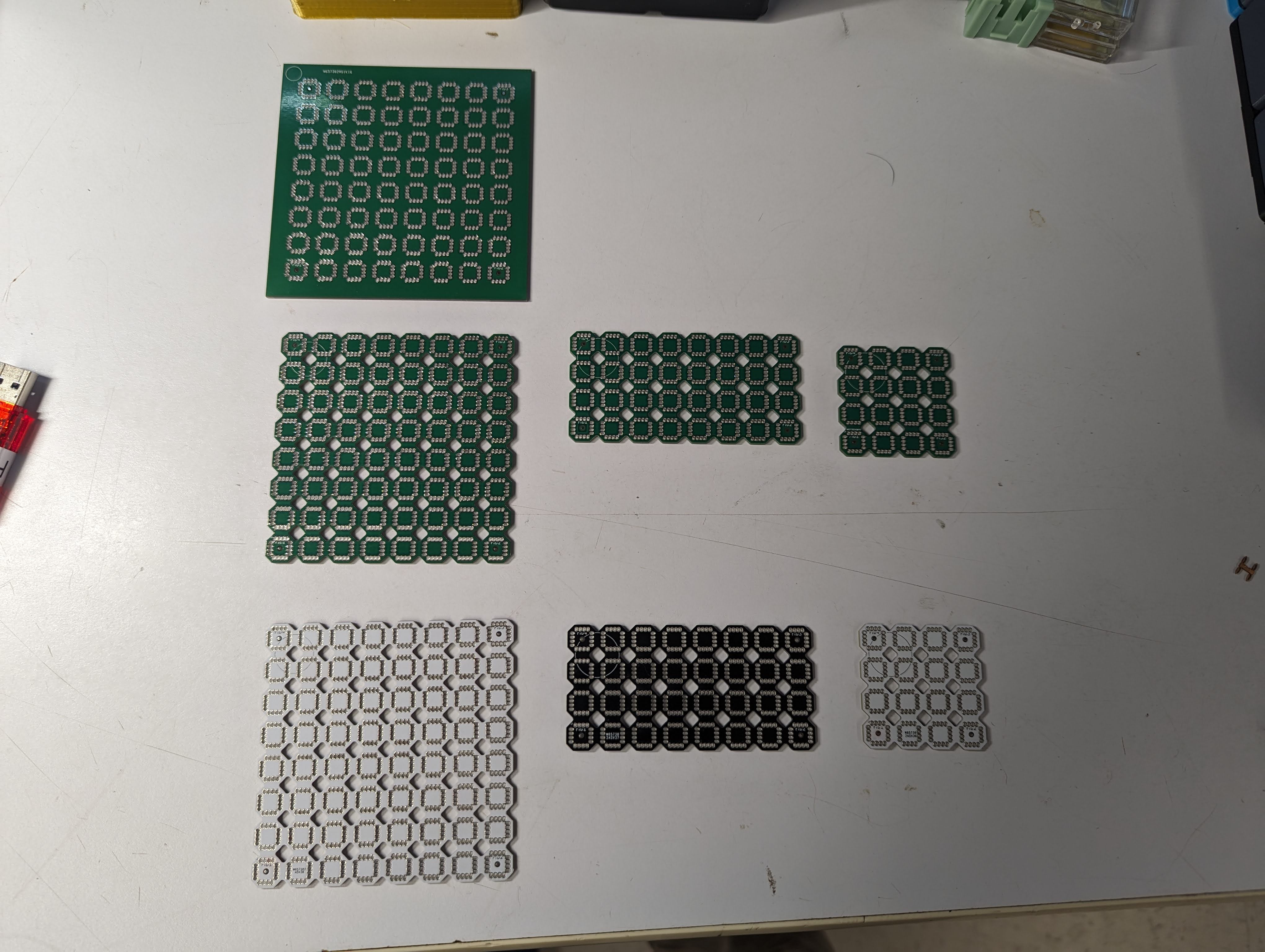
In contrast, the 4BI template is effectively a zero insertion force system. Some common configurations are shown in Figure 3.7.
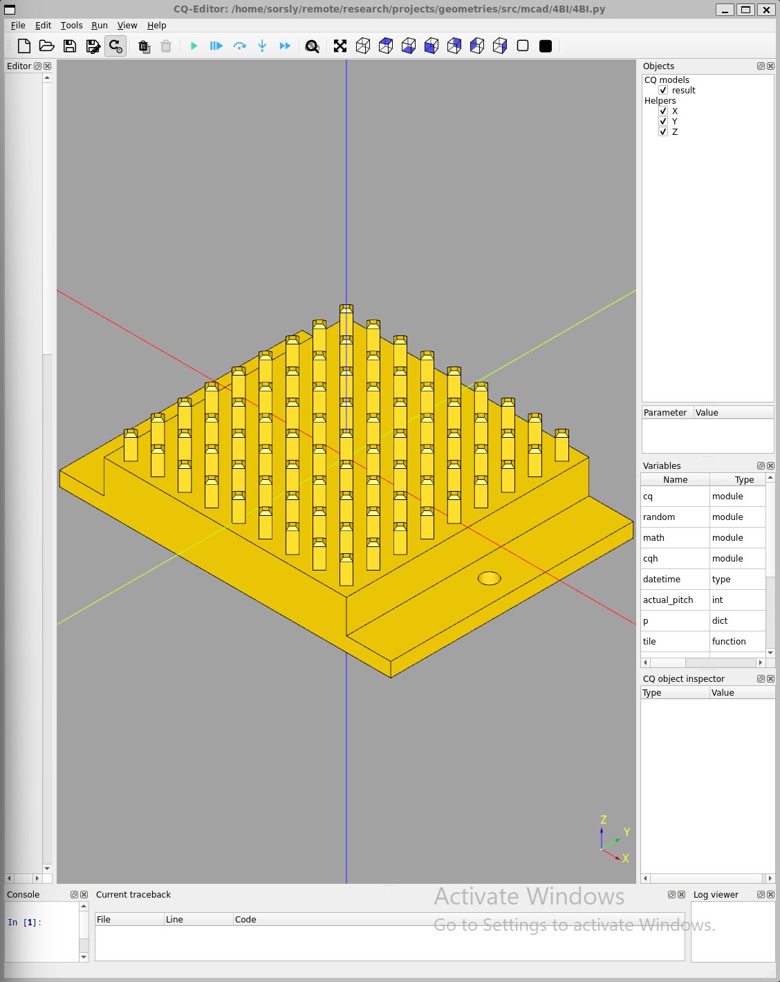
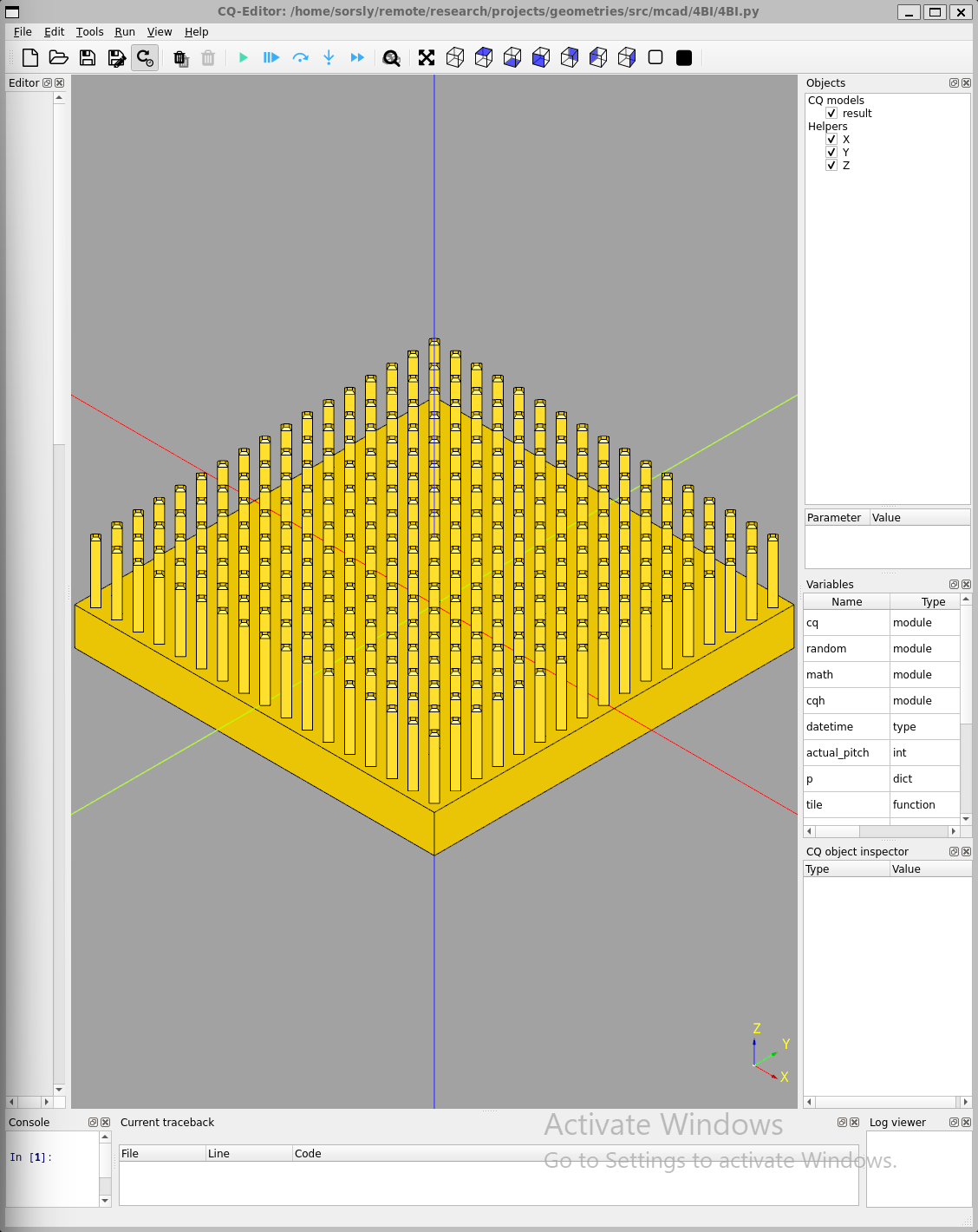
Like their counterpart feeders, 4BI templates were also initially designed using solidworks, then formalized with 4BI.py (cadquery). The current tradeoff between 4BI templates and 4Hp macro-tiles are that while the templates are easier to parametrically generate using 4BI.py, 4Hp macro-tiles are better at tesselation with standardized sizes. Adding this capability to 4BI is on the roadmap.
Initial templates used rigid pillars for locating and constraining tiles in xy, subsequent templates implemented compliant pillars that were more forgiving of coarser tolerances, and were important for maintaining pad to pad alignment.
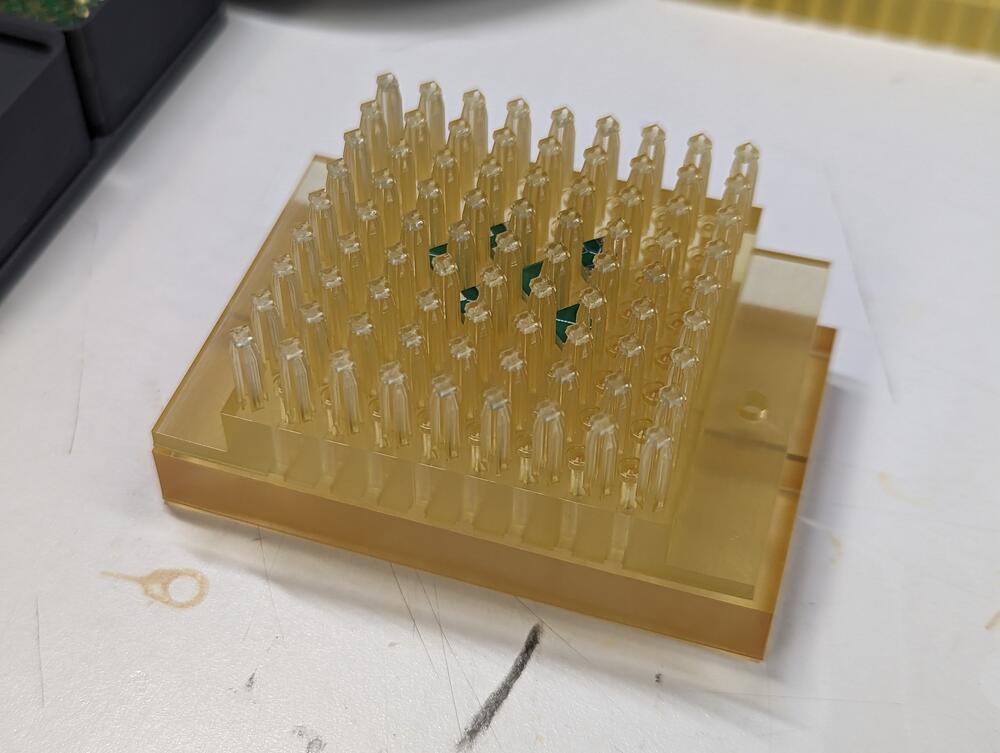
Over the course of these two jobs we identified problems as well as solutions to increase reliability necessary for automatic placement and avoiding the need for manual intervention. Initial templates featured rigid, non-compliant pillars that ran into tolerance issues; too tight and tiles would bind on the pillars, preventing proper seating and removal, too loose and neighboring pads would misalign and miss, resulting in open circuits. Subsequent templates adopted compliant pillars, which enable tighter tolerances. These new templates guarantee alignment and help retain tiles after placement, which makes assemblies less fragile.
4BI templates also require caps for compression to both preload the entire circuit and increase surface area of contact interface. This concept is similarly applied by [2] in his testing of active components in section 5.2.
3.4.3 Material Choice
During iteration, flexible, elastic resins were considered (such as Form 4 Flex 80A). While these materials offered excellent compliance, they unfortunately exhibited unwanted tackiness that interfered with assembly operations. In addition, the slow springback after deformation was too slow for reliably maintaining xy alignment.
After evaluation, we ultimately stuck with rigid resins with integrated flexures instead of fully flexible templates. This alternative provided more responsive mechanical behavior with less surface adhesion, without compromising the structural rigidity needed for effectively constraining the system during assembly.
Another variation was the Form 4 High-Temp resin. This variation was used for solder experiments, where 4BI tiles were loaded with solder prior to assembly, then subject to compression and heat to initiate reflow. For implementing this approach, High-Temp resin was required, even for low-temp BiSn solders @ 138C.
3.5 End Effector
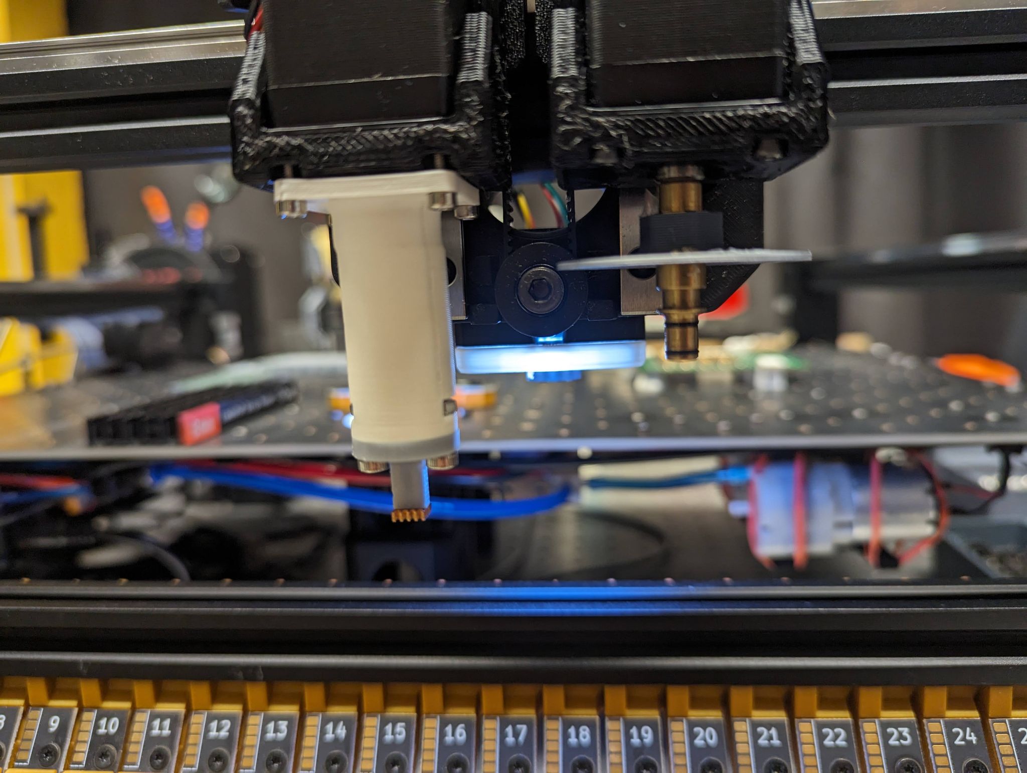
End effector went through multiple design iterations, but ultimately with both element consolidation and proven effectiveness from stock solutions, the standard vacuum end effector with stock N24 nozzles has persisted up to 4BI.
3.5.1 Claw Gripper
For 4Hp, a claw gripper design based on Zach Fredin’s design for Meso-DICE was implemented, targetting tiles. This design uses a cam driven by a servo to guide the fingers of the gripper in and out of compression with a tile.
These systems both utilize a bottom camera for registering tiles to the global grid and a load cell for verifying successful placement of elements.
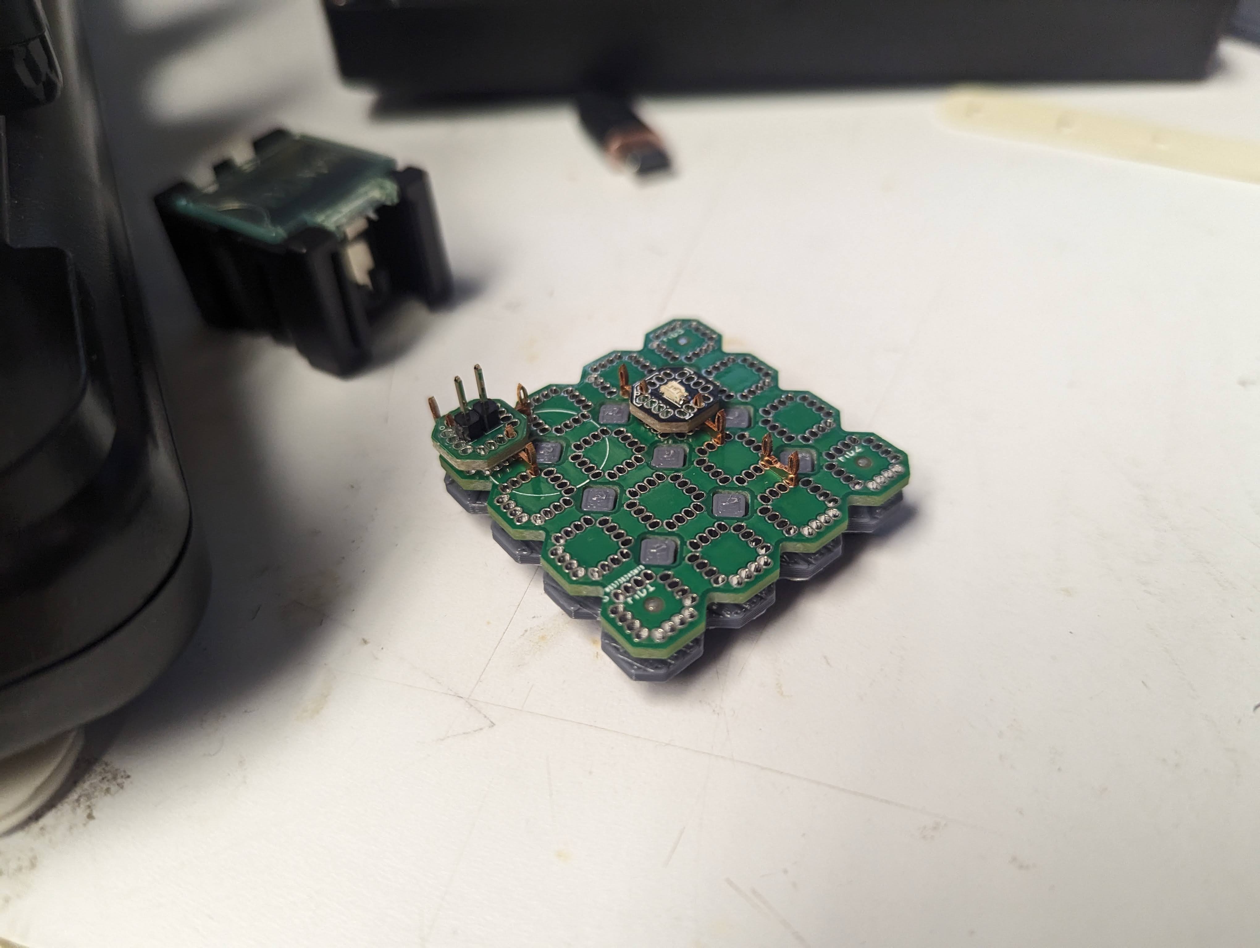
Although the vacuum pick-up strategy is sufficient for adding tiles to a structure, it doesn’t work well for removing tiles from a structure. We have created a prototype claw end effector, which aims to effectively both add and remove tiles, shown in Figure 3.9. Future work will extend the automated assembly to 3D, and begin increasing the component count.
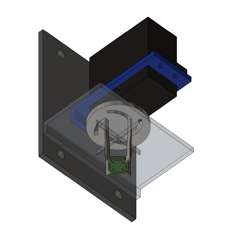
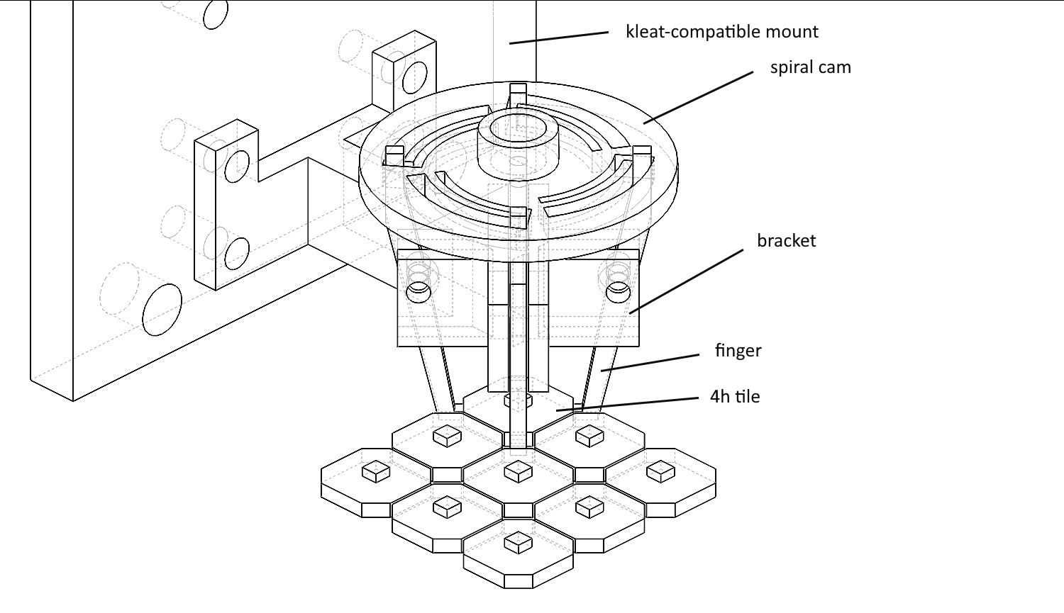
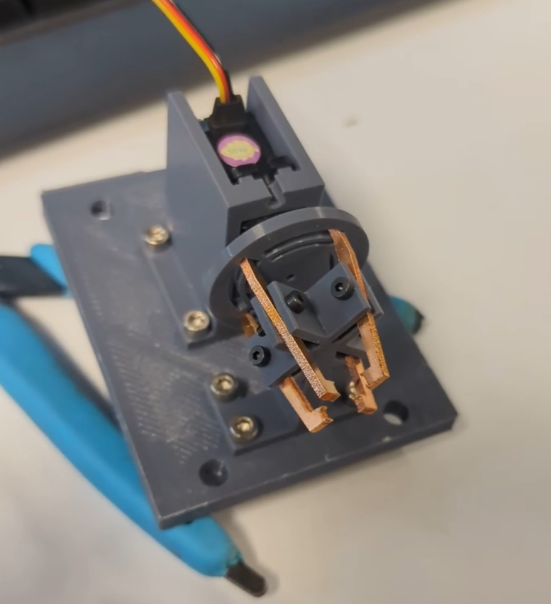
Several gripper iterations targeting the 4Hp geometry were fabricated, but due to binding issues and effectiveness of the vacuum nozzle approach, the claw has been parked for now.
3.5.1.1 Passive H-gripper
An early 4Hp H-eon concept used an electromagnet actuation strategy to clamp and unclamp elements was aimed at the H-eon connector. Later, this approach was simplified to a passive gripper, matching the profile of the slots in the tiles themselves and relying on the compliance of the H-eon connector itself for pick-up, shown in Figure 3.10.
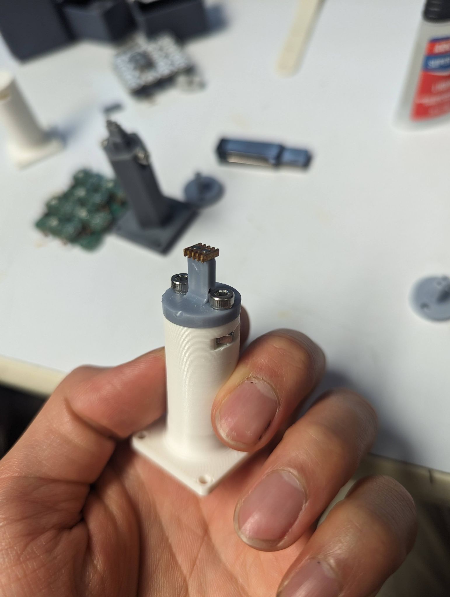
Since moving to 4BI and beyond, there hasn’t been a need for the H-eon end effector.
3.5.2 Vacuum Nozzle
Yohan Guilamard worked on custom multi-orifice nozzles targeting corner pads on 4BI.
3.5.2.1 Registration and Alignment Strategies
Our initial design assumed the nozzle would deflect during approach, providing a form of elastic registration. However, the final solution involved designing the template to deflect through carefully engineered flexures, which significantly reduced misalignment issues during the assembly process.
3.5.2.2 Nozzle Material
Stock nozzles are made out of steel, which are physically robust to shocks, which can be somewhat common in the assembly iteration cycle. This is especially true of the thin walls and small channels. However, stock nozzles don’t assume high anisotropic placement (deep placements), so combining stock nozzles with 4BI templates leads to compromises (with 1.6mm tiles, this is a limitation of 5-7 layers, depending on template alignment feature overhead, such as chamfers for the first 2 layers).
More durable resins may also improve performance and make this feasible; Black V5’s strength properties are insufficient for the job, they are too brittle. Flex 80A deforms elastically rather than breaking, but we found this material too sticky, which is problematic for consistent pick and place (emphasis on the place).
3.5.3 Sealing the Vaccuum
We identified an important assumption mismatch regarding tile materials. Milled FR-1 tiles typically lack soldermask, which can lead to gaps between copper traces and milled channels, potentially compromising vacuum pick-and-place efficiency. Despite this theoretical concern, the LumenPnP system demonstrated consistent performance between both FR-1 and PCBWAY FR-4 tiles (with soldermask). However, other suction systems experienced reliability issues with pick-and-place operations, either due to nozzle geometry (not completely flat, or conformal) or due to reduced air flow from less powerful pumps.
3.5.4 Nozzle Geometry
Due to unwanted tilting with the stock nozzle, time was spent looking into optimizing the nozzle geometry to enforce planarity of the tile.
Optimal nozzle geometry spans most of the tile surface area, with contact points strategically positioned at corners to ensure even distribution of forces and promote planarity of the tile during handling. Supporting complex geometries can introduce asymmetry, especially when incorporating fine features such as small channels and thin walls—both common elements in vacuum pick-and-place nozzles.
During experimental comparisons between stock nozzles and custom-designed alternatives, we observed that tile stability remained good as long as the resulting contact plane (comprised of single or multiple orifices) covered a majority of the tile’s surface area. For stock nozzles and 4BI geometry, N24 nozzles are the best fit.
A possible iteration that would remove the limitation within this system (7+ layers) would be to make a custom nozzle that extends the geometry of the stock N24 nozzle, using a metal fab process (possibly outsourced, likely machined by eg PCBWAY CNC).
3.5.5 Tile Surface Planarity and Area
Additionally, elements explored in this thesis have all been components on top of the tile. This makes a big difference in contact surface area for the vacuum end effector; picking the bare PCB maximizes surface area and enables us to use the N24 nozzle, while picking the side with a component either forces us to use a much smaller nozzle (N45) or use a much larger nozzle to fit the component inside the nozzle (N08), which ironically has restrictions fitting inside the template itself.
In a future iteration, integrating the functionality into the tile would offer more flexibility (much like an IC that behaves in a VMD, rather than SMD, manner).
3.6 Error Correction
Statistically speaking, in the case of scaling from 10s to 1000s of parts, it’s not a question of if defects will occur, but rather how many defects will occur. Robust error correction mechanisms are required to properly assemble circuits that function at scale. There are multiple strategies to address these issues: error correction during assembly, error correction after assembly, and ease of assembly/disassembly to such that these solutions are practical.
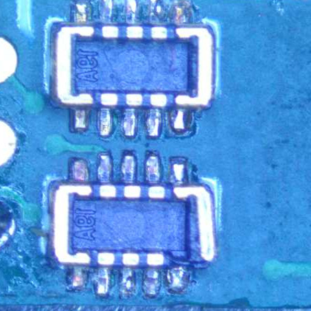
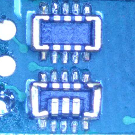
During assembly, it has been observed that tiles can be placed incorrectly, resulting in a few different error states, such as the ones in Figure 3.11.
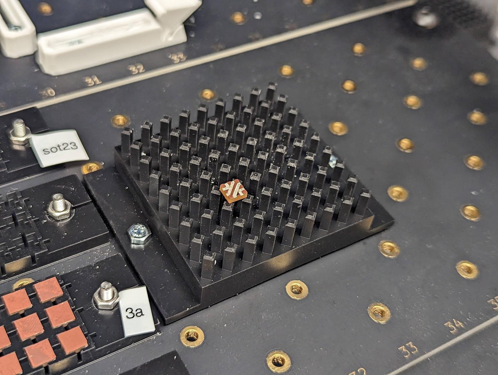
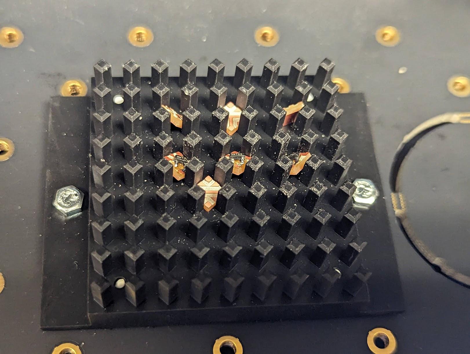
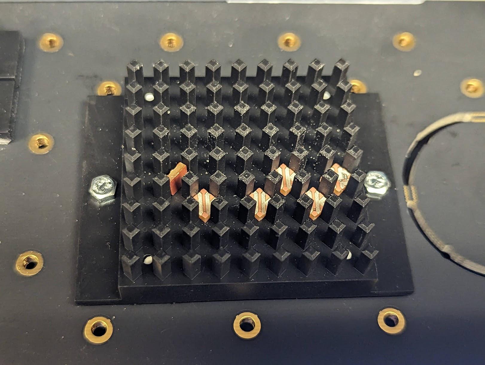
These error states range from inconvenient to catastrophic; some errors demonstrate an ability to recover while others prevent neighboring tiles from achieving a valid state. These errors can be largely mitigated by robust error correction mechanisms during assembly. The current approach heavily relies on computer vision for orientation and center detection of tiles in order to pickup from the feeder and correctly place into the template. This resolves to properly recognizing the boundaries of the tile which is usually based on sufficient contrast of identifying features; in this case reflection of conductors facing the camera. For purely mechanical tiles, reflection of the bulk substrate is the identifying feature (eg white resin performs while black resin lacks sufficient contrast). By improving estimation of these features and making sure angle corrections are carried out within tolerance, many of these scenarios can be avoided.
Additionally, end effector geometry plays a significant role in distributing forces evenly during pick-and-place operations. For instance, using a larger N24-sized nozzle covers ~70% of a 4BI tile’s surface, providing more stable support compared to an N08-sized nozzle that only covers ~25%. When the tile is supported at a single central point, such as with a small nozzle, it is more susceptible to tilting or rotating due to uneven force distribution and higher moments at the edges, especially if a collision occurs with an alignment pillar. An example of a tile tilting due to uneven solder and small contact surface is shown in Figure 3.12 (a). In contrast, supporting the tile at multiple points, like its four corners, reduces these moments and helps maintain stability when placing the tile into a container, as shown in Figure 3.12 (b). Uneven soldering also introduces errors exacerbated by central support versus edge support.

A 2-fold approach for coarse and fine positioning of geometry is useful for reducing error correction defects and improving scalability; for example, converting the pillars in the template to improve compliance reduces tolerance requirements for coarse positioning, while the pillars themselves are used for fine positioning.
Post assembly, it has been observed that poor tolerance stackup contributes to accumulated error, eventually leading to intermittent contacts. One possible solution is following a physically hierarchical approach; individual templates are parametric and can be sized such that a limited number of tiles are placed (eg 4x4x4 or 8x8x8), and finished block assemblies then assembled together to form a much larger assembly. The faces of the block assemblies operate as interposers that then pass signals and power across blocks; the interconnect system here can be designed for quick and robust connection/disconnection to troubleshoot and correct malfunctioning blocks.
3.6.1 Overconstraint and Compliance
Part alignment is key towards functioning circuits, local (part-to-part) and global (template-to-part) alignment have been the two main strategies. Deciding between the two strategies impacts tolerance stackup. If tolerance stackup is not properly managed, physical defects can occur due to misalignment and undermine mechanical and electrical performance. An example from Tiny-DICE is in Figure 3.13.
3.7 Comparative Assembly Rates
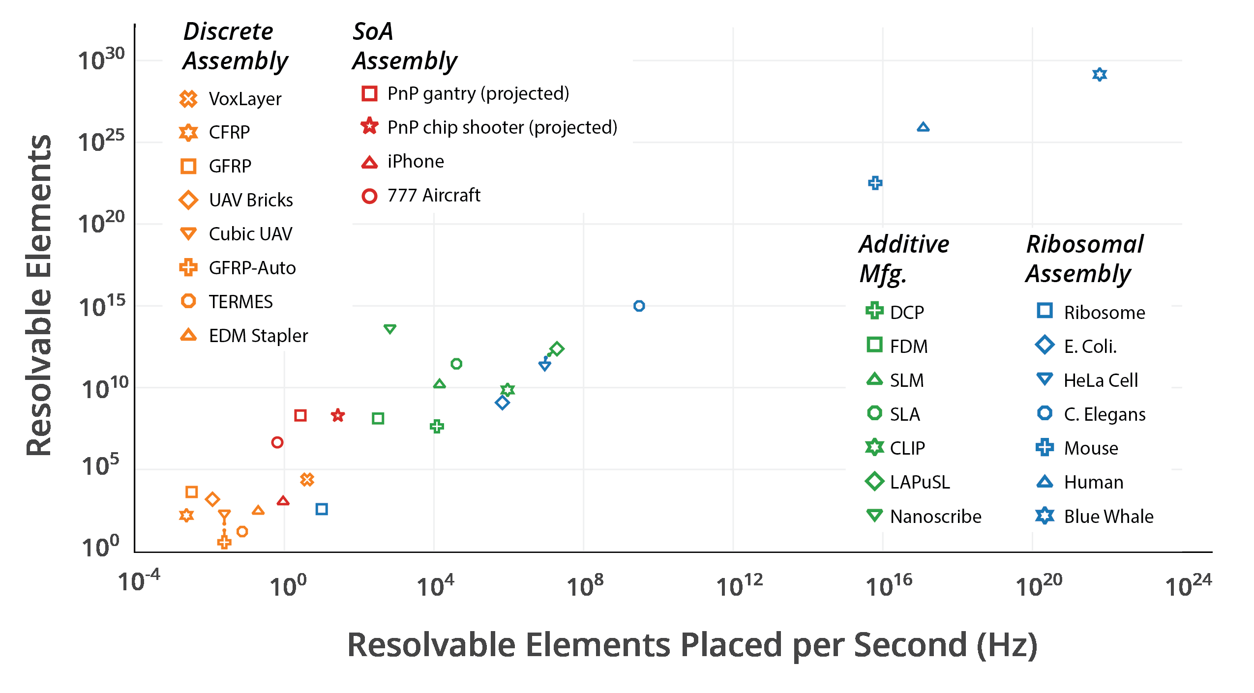
Will Langford’s analyzed relative rates of assembly between natural and artificial means (Figure 3.14), showing the capability gap that needed to be crossed to reach parity with resolution vs number of elements assembly [5].
Although we are not yet ready to address the massively parallel assembly implications from Will’s thesis, we can still derive reference points for contextualizing our own assembly throughput; in his chart, commercial pick and place machines are projected to be among some of the highest throughput artificial means of assembly. Although all referred to as pick and place machines, there is a wide range of capability, covering different regimes.
| Machine | Claimed CPH | Technology / Notes |
|---|---|---|
| Hand Assembly 1 | ~100 | Manual placement by human operators. |
| LumenPnP [6] | 1,580 | Open-source, DIY-friendly desktop PnP. |
| Neoden 3V [7] | ~5,000 | Budget small-batch machine. |
| Juki RS-1R [8] | ~42,000 | High-speed modular industrial machine. |
| Fuji NXT III [9] | 35,000–37,500 | High-end modular system; each module rated. |
| Yamaha YSM40R [10] | ~200,000 | High-speed modular rotary head system. Discontinued. |
| ASM Siplace SX [11] | ~80,000 per gantry | Industrial, configurable for very high speeds. |
From Table 3.1, there are a few rates that carry special attention. For most of the related work section discussed in Chapter 1, and most of the iterative work required to build to this thesis, Hand Placement was the primary driver for circuit assembly. Even as assembly improves, augmenting Hand Placement for semi-auto rather than full-auto solutions may be beneficial for iteration, especially if tile geometry changes significantly and requires new end-effectors. Often, effective hand tools translate to effective end effectors, and vice versa.
From here, we move on to the LumenPnP itself. The current actual PnP speed observed from various PnP jobs is about 2/3rds of the advertised max; the LumenPnP head itself is capable of 2 nozzles instead of just 1. The typical end effector configuration uses nozzles of two different sizes, which is likely used to achieve the advertised max for standard PCBs. In our case, we may need to install two N24 nozzles to achieve the advertised max for assembling circuit volumes.
Finally, the Yamaha YSM40R serves as a theoretical conventional limit for PnP throughput. This highly specialized PnP is no longer sold, but holds the record for fastest PnP that has been commercially available. More modular models have since taken its place, though they have a lower throughput, they are more flexible for reconfiguring to different types of jobs.
These rates of interest have been consolidated in Table 3.2.
| Description | CPH (Components per Hour) |
|---|---|
| Hand Placement | ~100 |
| Current Actual PnP Speed | ~1,000 |
| LumenPnP Advertised Max | ~1,500 |
| Yamaha YSM40R (Discontinued SOTA) | 200,000 |
Using these selected PnP rates, a projection tradeoff can be made, optimizing for increased serial speed, or increasing the number of machines in parallel, or both. Projections are shown in Table 3.3.
| Scale | 1x Machine | 10x | 100x | 1,000x | 10,000x |
|---|---|---|---|---|---|
| 1x current | 1,000 | 10,000 | 100,000 | 1,000,000 | 10,000,000 |
| 2x current | 2,000 | 20,000 | 200,000 | 2,000,000 | 20,000,000 |
| 5x current | 5,000 | 50,000 | 500,000 | 5,000,000 | 50,000,000 |
| 10x current | 10,000 | 100,000 | 1,000,000 | 10,000,000 | 100,000,000 |
3.7.1 Possible Parallelization Pathways
Increasing assembly throughput can be accomplished through several distinct approaches. One method is to increase serial speed for a single assembler, which can be achieved by transitioning to a stiffer motion system capable of handling faster speeds without sacrificing resolution. Low-backlash systems could enable this improvement; the effectiveness is heavily dependent on the specific motion system and hardware implementation. Fundamentally, there is a tradeoff between speed and precision, which sets a hard limit on how fast a machine can usefully go.
Another approach involves implementing simultaneous parallel pickup from a single end effector. This strategy could dramatically increase throughput; however, it presents a challenging control problem to ensure reliable selective pickup for each element being handled. Additionally, this method may introduce more motion overhead to coordinate elements into the correct location for the assembly head.
The VoxJet system exemplifies an innovative parallel assembly approach. Developed by Hod Lipson and Jonathan Hiller, this VoxJet precursor utilized acrylic non-conductive (and conductive, though not emphasized in this context) spheres as building elements with inherent self-aligning properties. The system employed an electrostatic end effector capable of manipulating multiple elements in parallel, reportedly handling thousands of insulating spheres simultaneously [12] [3]. There has yet to be a way to apply a similar approach to integrated devices for 3d volumes, which is what this VMD approach aims to satisfy.
Finally, reducing the cost of individual assemblers and deploying multiple systems operating in parallel can effectively balance the performance limitations of any single machine. This approach offers additional benefits including increased feedstock flexibility and enhanced redundancy in case of assembler failure. However, it introduces a different category of challenges, shifting focus from coordination within a single machine to sophisticated orchestration between multiple assembly systems.
In the next chapter, we evaluate the joint and circuit performance of these geometries. Additionally, projections are made for scaling the feature size down, which will be necessary for increasing achievable VMD performance.
Note that it was difficult finding a source for manual placement CPH; instead, 100 CPH is conservatively estimated from my manual placement job for the 4BIc0 full-adder, which was ~150 tiles in ~55 min.↩︎